Technical Details
We've solved MRR(VFA)!

Have you ever seen this pattern in your prints? People usually call it Vertical Fine Artifacts(VFA). But according to our research, we believe Motor Resonance Rippling or MRR is a more appropriate name.
If you are interested in technical details, please continue.
Or you can visit our product page to get the most suitable upgrade kit for your Original i3.
How common is MRR?
Like us, many Original i3 users have experienced MRR(VFA). But what about other printers? We tested off the shelf printers from Ulti***er and Cr****ty; our Original Mini; open sourced DIY ones like Voron. Here are our results.

ALL of the printers we tested have MRR except with different MRR terrible speed ranges.
One of our friend in the industry tells us even the machine from the oldest Industrial 3D printer company has serious MRR.
What triggers MRR?

When will MRR show up?

You can see a clear resonance peak near the speed in QUALITY preset in slicer software and how MRR changes as the printing speed approaches and passes the peak.
There is a dramatic coincidence about Original i3
Here is the speed sweep result of the Original i3 with two other printers. As you can see, the printing speed in the QUALITY preset of the slicer software is almost the MRR max speed of Original i3.

For other printers, their default settings happen to avoid their MRR terrible speed ranges. This is why Original i3 users have a higher chance of finding themselves troubled by MRR compare to others.
Our solutions for MRR
Method A: Tune the printing speed
We can adjust the printing speed to avoid the MRR terrible range. You can find our integrated profiles here. However, this method sacrifices a lot of efficiencies to gain some quality and here is why:

During printing, the nozzle traverses the lines in layers. When the nozzle moves in both X and Y directions. The net printing speed is a combination of both X and Y speed as shown above. So for any i3 style machine, the X speed or Y speed is always less or equal to the printing speed.

This means with the speed In QUALITY preset, the XY speed range will overlap with most of the MRR terrible speed range. Boosting the printing speed makes prints better only if the surface is along the X or Y-axis. For any other surface shape or at corners where the nozzle needs to decelerate. The X or Y speed will be slower and hence falls in the MRR terrible speed range. Thus the only viable solution here is to significantly lower the speed to gain quality.
Method B: Optimize the motor, Suppress vibrations

We can reduce MRR directly from the source. According to our study, under the same printing conditions, the motors with smaller characteristic vibrations generate less MRR. As you can see from the graph, M brand motors have less MRR than stock ones in general. So we tried to optimize our motor to suppress these vibrations. With sufficient tests and research, we managed to reach a significant reduction of the vibration. Unlike method A, we do not have to sacrifice any efficiency.
Method C: Raise the natural frequency of the frame

Another way to reduce MRR is by raising the natural frequency of the frame. A much higher natural frequency means the characteristic vibration will not be able to resonate with the frame. The vibrations without resonance enhancement will be much smaller and thus MRR greatly reduced. This method is very effective when combined with Motor vibration reduction in Method B.
Other than MRR: The pattern from belts and pulleys
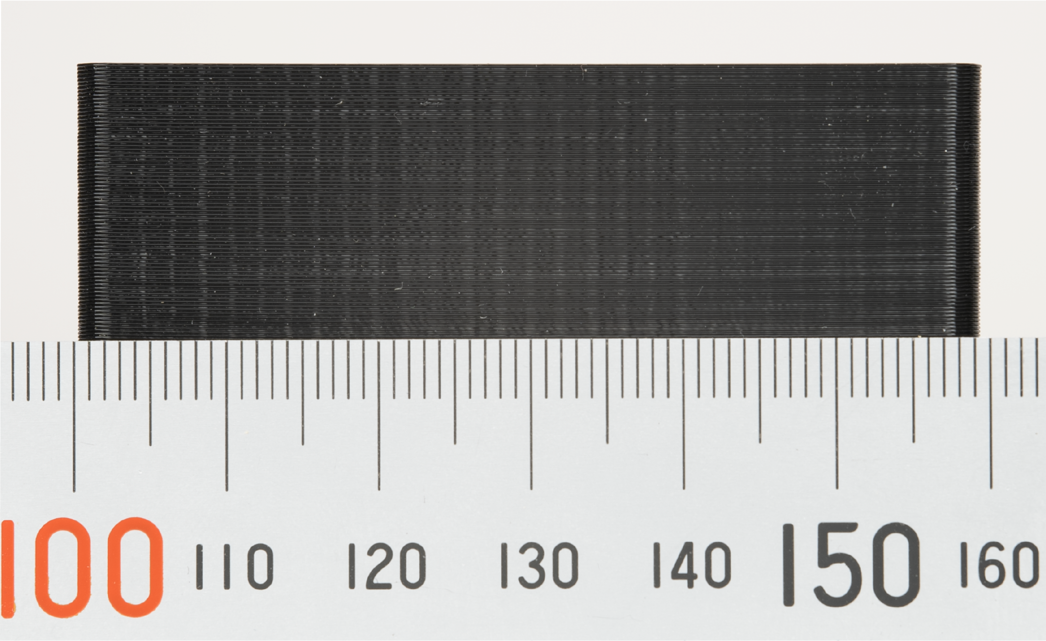
When MRR is solved, you may spot these patterns on your prints. Although it looks similar to MRR, this pattern has a distinct separation same as the pitch of the timing belt and is caused by the polygon effect from the belt and pulley system rather than vibrations from motors.
What is the Polygon effect?
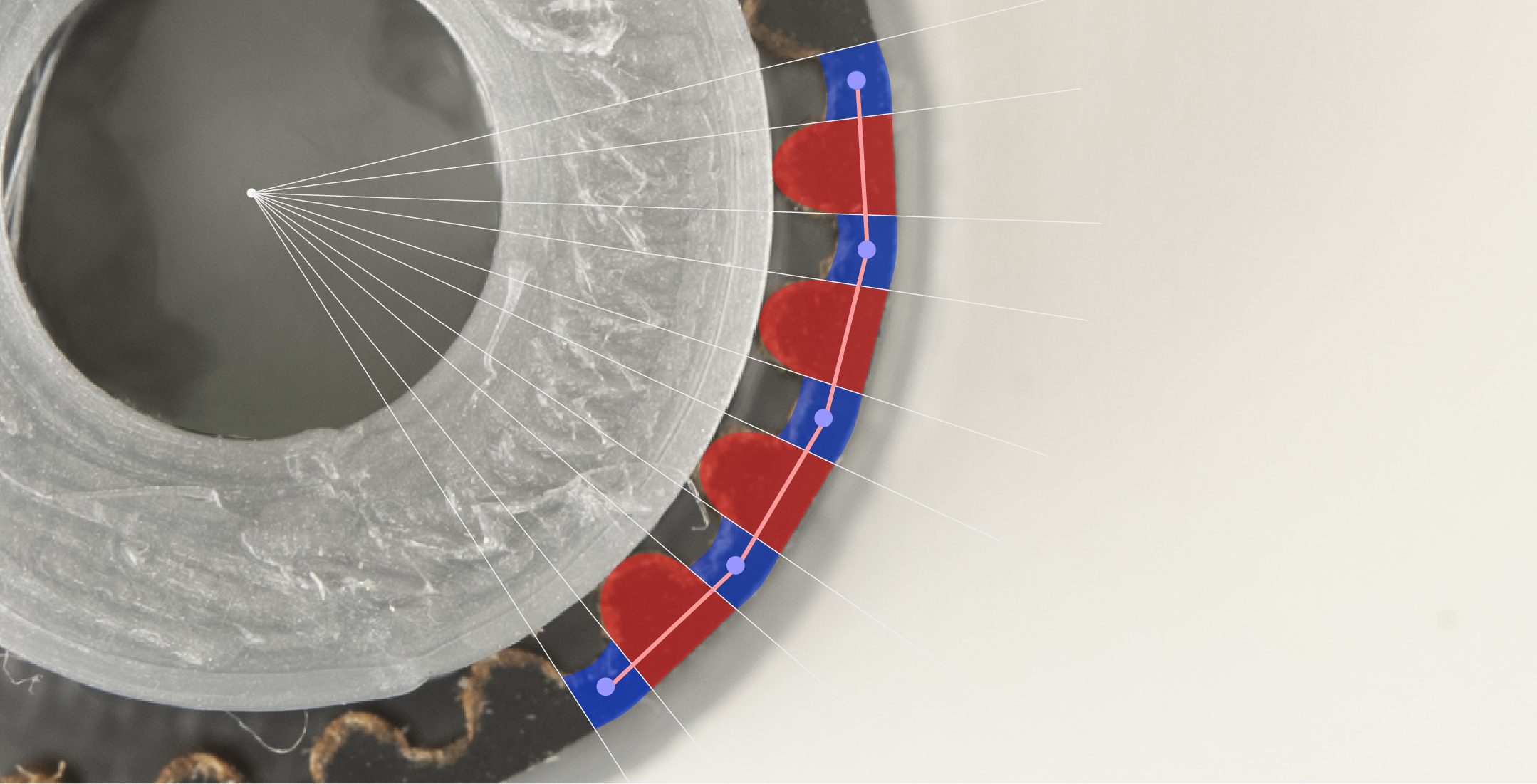
The teeth on the timing belt are thicker and thus harder, the gaps are thinner and thus softer. When driven by the pulley, the "hard" section bends less and the "soft" section bends more. This will cause the "Polygon effect" that makes the belt-driven system movement non-uniform and hence change the extrusion width, causing this distinct pattern.
Our solution: Dual belt with phase shift
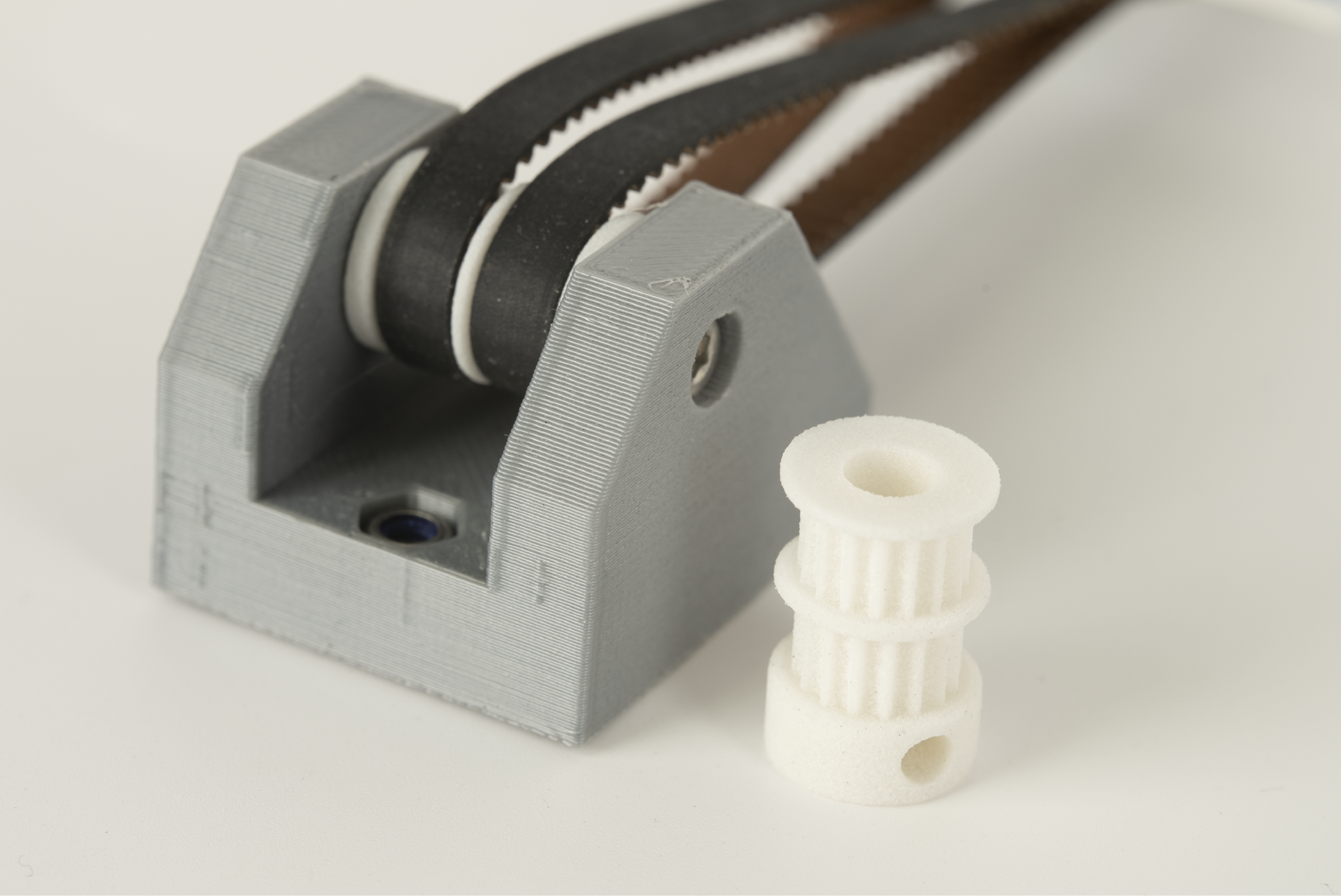
To mitigate this polygon effect we can make two belts shifted by half pitch which is half the period. By doing so the belts can compensate each other during movement and hence weaken the polygon effect.
A Dual belt is also stronger and stiffer than a single belt. This can also reduce ringing and boost the overall performance.
Visit Our Github
